|
wireless HCI |
|||
|
- page last modified, March
2013- (página en
castellano)
|
|
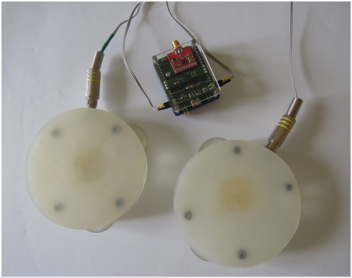
In this project I reuse the PCB nRF24. This battery powered circuit I designed to have a wireless reusable system that allows to plug in small satellite PCB's for any future needs. In this case, to build a HCI (human computer interface), I designed a small PCB with two envelope followers. One can strike the pads (see photo) by hand or sticks, as one could do with a drum pad. With a resolution of 10bits one get a very precise control of the calculated data of the PIC (18F4420). On the bottom of this page is a link to a ZIP file that includes the MPLAB files & the schematics for the envelope follower. |
 |
| a simple and nice working envelope follower |
|
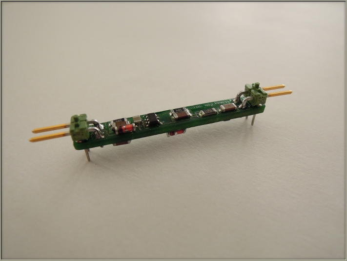
To make something meaningful for the analog input of the micro-controller, the raw data captured from the transducers have to be treated (filtered) with an envelope follower. The picture shows a PCB with two envelope filters (followers) incorporated. The PCB is designed as satellite to be connected on a base circuit look here.Using SMD (surface mounted devices) allows to build a very small electronic circuit that allows, on the other hand, the use of all possible analog inputs of the base-circuit. |
 |
 |
| The circuit is
quite straight forward. Using a rail to rail single OPA336 with the positive input, pin 3, connected to GND, the op-amp amplifies only the positive part of the incoming signal. As the goal is to get the envelope of the signal (a variable DC signal) only one diode, a 1N4148, is used to forward the positive signal achieved from the piezo-transducer. The voltage charges C3 and discharged through R3. The time constant is with 56k and 470nF aprox. 25ms. Increasing the values of R3 and C3 increases the decay time. As I use the circuit to trigger a self made PAD I use a small discharge time of 25ms . As we are not interested in signals above 1000Hz the feedback (R1, 100k) of the op-amp is in parallel with a small capacitor of 2,2nF. The cutoff frequency is about 720Hz. To improve the sensitivity a Schottky diode can be replacing the 1N4148. For my use I connected a 56k resistance in serial with C1 to dump the amplification. |
|
| construction of the pads |
|
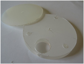
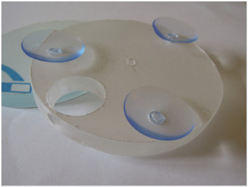
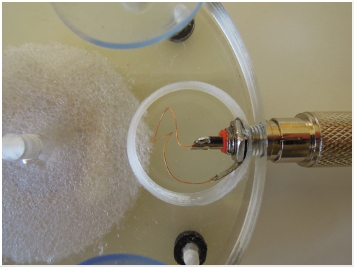
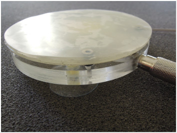
The base is a rigid Plexiglas-disk with a thickness of 10mm. Using a drill with a krone of 100mm the circle gets perfect. To fix the plug (RCA), that is used to connect the transducer, a whole of 23mm, and another smaller one of 6mm (diameter of the RCA), is drilled on the side of the disk. The transducer is hold in place simply by a dish-clean rubber between the base disk and a thinner, rigid plastic disk of 5mm. Three screws of 3mm avoids that the disk want fall apart. |
 |
 |
|
The top layer (the one how is hit) consists of a silicon-rubber of 5mm. The stick bounces better if the upper silicon-rubber is doubled. Using silicon glue works well, so that the rubber want fall apart. Another three small rubbers separates the ground disk with the 5mm rigid disk for the transducer. Three 3mm screws holds the two disk in place. I made both pads in a afternoon, but the best are the rubbers from the Chinese drugstore that avoids the dancing of the pads when playing with “fire”. |
  |
|
|
 |
download the files for MPLAB & the envelope
schematics |