|
|
tech.description of the OSC/MIDI controler | ||
|
-
page last update september 2009--(página en
castellano)
|
|
The entire project, including all electronic schematics, the C and the HEX source code for the PIC 18F442 microcontroler, as well as all electronic schematics of the circuits and the program written with PD (pure data) can be downloaded as a ZIP file at the bottom of the page. |
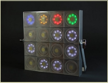
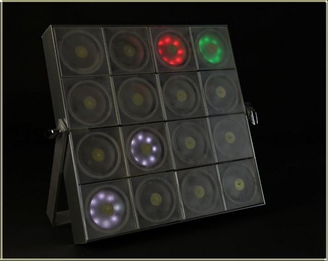
| wireless panelto control OSC and MIDI messages with Pure Data. |
 |
 |
|
photo el Ravallero
|
|
The electronic circuit of the panel transmits data over a
wireless connection (using xBee modules) to a small “HOST”
(Rx_Pad_to_HOST) circuit. The HOST circuit is connected trough a level
shifter ((MAX232_UART) to the RS232 serial port and a program written
in PD (pure data) manages the incoming/outgoing data. |
| capture the hits of the panel |
|
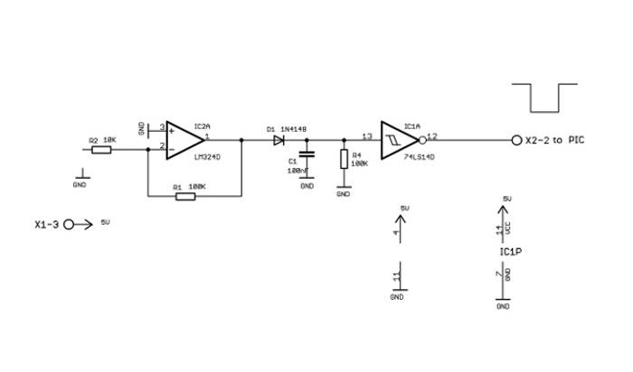
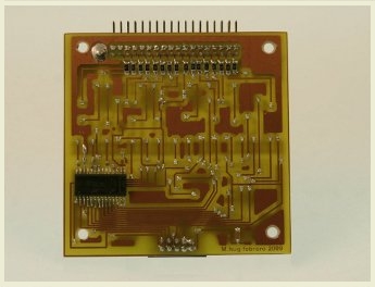
Trigger 74HC14: To capture the signal of the piezoelectric-transducers I
designed a simple, but efficient circuit using a LM324 as a
preamplifier and a 74HC74 Schmitt-Trigger to convert the signal to a Hi
or Low. For the use with the panel the amplification needed is very
low. (G = R1/R2). I use for R1 1M ohm and R2 560k ohm. So, the
amplification is aprox. 2. With this values I get brilliant results in
sensitivity without having problems with interfering other Pads. The
D1, 1N4148 together with the condenser C1 of 100nF and the resistance
R4 of 100k ohm have the function of a very simple envelope follower.
The 74HC14 acts as an inverter, so that the signal at its out (Pin 12)
have logic Hi. This has the advantage that the IC can be connected
without worrying of pull-up resistances to any PORT of a
micro-controller. |
 |
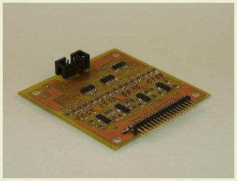
| Pad_trigger to connect 16 piezo-transducers. |
 |
 |
|
photo el Ravallero
|
|
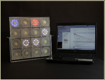
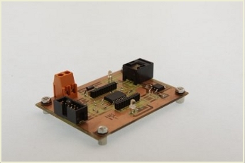
The Pad_18F442_xBee: As mentioned above trough PORTA RA0 - RA3 the multiplexer
DG406CWI is scanned constantly. If a low is detected on PORTC, RC2 the
18F442 sends a number ( I use 48 to 62) to the UART of the PIC to the
xBee module. The xBee sends the data to the receiver-module
(Rx_Pad_to_HOST) and from there trough a level-shifter MAX232
(MAX232_UART) to the serial port (RS232) of a computer. |
 |
|
photo el Ravallero
|
|
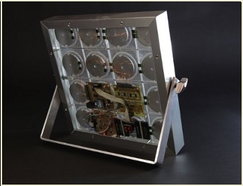
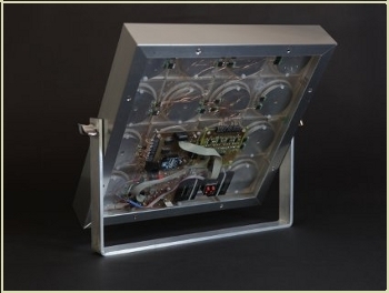
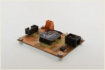
PW_PAD_USB (power_management). The circuits are powered by two UNIROSS 3,7V 1080mA
batteries. One is used to drive the LED-eyes, and the second battery
powers the 18f442, xBee and the Trigger-PCB with the DG406CWI
multiplexer. Using Christmas lightning (every PAD is illuminated), 16 * 8
LED's are lighted up, the circuit needs 300mA.
|
 |
 |
|
photo el Ravallero
|
|
enlarge the electronic schematics of the
"Pad_trigger_HC14"
|
|
|
enlarge the electronic schematics of the
"Pad_18442_xBee"
|
|
|
enlarge the electronic schematics of the
"PW_PAD_USB"
|
|
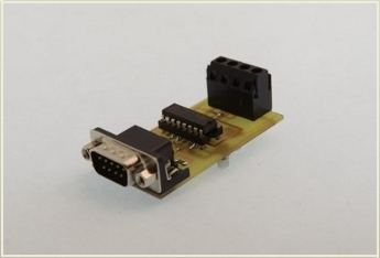
| Rx_Pad_to_HOST |
 |
 |
|
photo el Ravallero
|
|
Rx_Pad_to_HOST; |
|
enlarge the electronic schematics of the
"RX_Pad_to_HOST"
|
|
| MAX232_UART |
 |
MAX232_UART:
|
|
enlarge the electronic schematics of the
"MAX232_UART"
|
|
|
|