|
technical description of the "Midi-Stick" |
|||
|
-
page last update october 2007 - (página en castellano)
|
|
The entire
project, including all electronic schematics, the ASM and the HEX
source files of the PIC 16F877 and PIC 16F628A microcontroller, as well
as the PDF of the SRF02 (ultrasonic sensor) and ER400xxx can be
downloaded as a ZIP file at the bottom of the page.
|
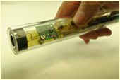
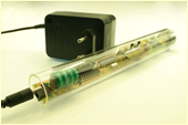
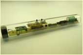
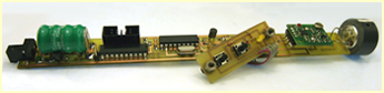
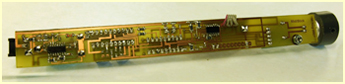
| MIDI-STICK with SRF02, ER400TS-02, 16F628A and MAX712 batterie charger |
 |
 |
 |
 |
|
The SRF02 is an ultrasonic range finder that works with a
single transducer. Using only one transducer to both transmit the
ultrasonic burst and to receive the echo of the same, reduces the size
of the unit to only 20x24mm. The small size allows it to be easily
incorporated in a tube with a diameter of 25mm. |
 |
 |
|
enlarge the block schematics of the
"Midi_Stick"
|
|
|
enlarge the electronic schematics of the
"Midi_Stick"
|
|
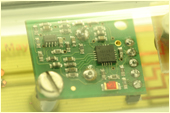
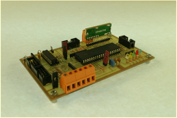
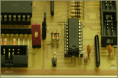
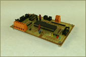
| HOST receiver with 16F877A, ER400TRS-02 and an In Circuit Programmer using the 74HCT573 |
 |
|
foto
Holger Strauss
|
|
Incorporated in the PCB (Printed Circuit Board) of the Host is a microcontroller 16F877A. The Pic controls the receiver (ER400TRS-02) and sends the Midi Data with a serial program routine to PortA. RA4. The ER400TS-02 and the ER400TRS-02 are made by LPRS (Low Power Radio Solutions). The company offers evaluation software (Easy Radio Evaluation Software) to program the modules. This software uses the serial port RS232. Connecting the modules to RS232 it is important to put a level shifter, MAX232 to avoid the destruction of the same because of different voltage levels. The ER400TRS-02 has a "fast ACK" available. In this way, instead of responding with text code "ACK", the answer is a single byte of 0x06hex, that is the ASCII value of ACK. In this way the changes of the configuration of the ER400TRS-02 accelerates remarkably. Like the SRF02 the Easy Radio modules have the speed set as default to 9600 bauds. Incorporated in the PCB of the Host is again a 74HCT573 to have the ability for ICSP (in circuit programming). As the Ports are connected to plugs and PortC is used for indication LEDs, the Host PCB can be used for other applications. |
 |
 |
 |
 |
|
fotos
Holger Strauss
|
|
enlarge the block schematics of the"Host"
|
|
|
enlarge the electronic schematics of the"Host"
|
|
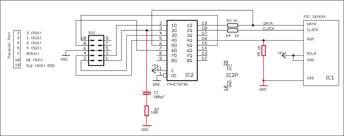
| ICSP LVP In Circuit Low Voltage Programmer |
 |
|
The ICSP LVP programmer (In Circuit Serial Programmer, Low
Voltage Programmer) or low voltage in circuit programmer http://finitesite.com/d3jsys/
was designed by Byron Jeff. For the necessities of this project the
circuit is slightly modified. (See electronic schematics above). Using
free-software WinPic for Windows http://www.qsl.net/dl4yhf/winpicpr.html
the ICSP works without any problem. The file “LVP.INI” has to be copied
to the subfolder "interfaces" of the WinPic program. The LVP.INI is
included in the ZIP file that can be downloaded from this page. The AC
terminator with C1 (100pF) and R2 (100 ohm) is important. The
resistance, R5 (390 ohm) has a pull down function at the PGM (Pin 36,
16F877A or Pin 4, 16F628A) and stabilises the Pic’s after they have
been programmed. |
| LVP.INI file to be copied into the subfolder "interfaces" |
|
[Info]
|
|
|
| The "Midi_Stick.zip" includes all schematics, HEX, ASM files, the file for the MPLAB (developement tool from Microchip) and the Data Sheets for the Ultrasonic Range Finder SRF02, the Easy Radio module ER400xxx-2 etc. |