|
Cristal externo de 20MHz.
// init function for RX/TX
void init_TX_RX()
{
char dump; // aux Var to empty RX_buffer
rcsta = 10000000b; // set SPEN bit,serial port enabled & CREN
disabled.
txsta = 00100100b; // TXEN enabled, BRGH = 1, TX9 8-bit, Async mode.
baudcon = 010001000b; // BRG16 = 1 (010001000).
spbrg = 42; // 42 for 116,279Kbaud)
dump = rcreg; // empty RX_buffer.
dump = rcreg; // empty RX_buffer.
}
//La función de un canal (canal 3) para enviar los datos mediante el
USART del PIC.
//Solo si las condiciones de la primera línea están evaluado en verdad
(true) la función envía los datos al USART.
if ((!test_bit (on_off,3)) && (Vel_3 >= TH_3) || (Vel_3
>= aux_3 + TH_3))
{
del_3 = del_3 + 1;
if (del_3 >= del_On_3) // short delay to adjust the envelpoe knee at
the beginning.
{
set_bit (portc,1); // white_LED on.
aux_3 = Vel_3; // aux_3 used to re-trigger Note. if value is higher
than Vel_3.
set_bit (upper_3,4); // select Ch_3: 10000b = 16.
init = 0x00; // init byte, sets in Pure Data the gate_object.
txreg = init; // 1st byte =0x00
initialize Pure Data.
while(!trmt);
txreg = upper_3;
while(!trmt);
txreg = lower_3;
set_bit (on_off,3); // indicates that data is sent.
del_3 = 0;
clear_bit (portc,1); // white_LED off.
Vel_3 = 0x00;
return;
}
Uff … it looks weird but it isn't …
The function shows how 10bits of channel 3 are sent. The
transmission includes in total 3 bytes: The init
byte, always 0x00, the bytes upper_3 and lower_3.
The 6 unused bits of the upper byte of the 10bit AD conversion are used
for direction purpose. So, locking at the code above the “set_bit
(upper_3,4)” writes the address, so that Pure Data (or Prozessing) can
extract the address included in the upper_3 byte and assign the
corresponding channel.
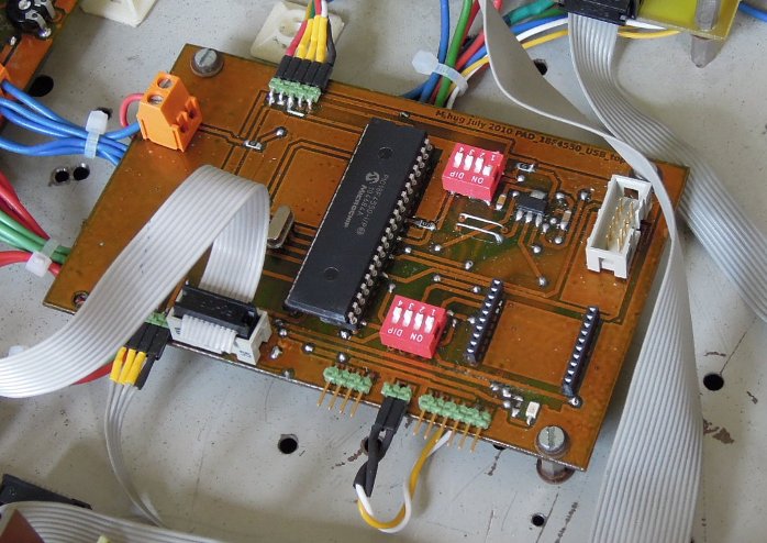
To determinate an event a forth byte is sent, As soon as the 18F4550
reads a 0V at the analog input a byte with its corresponding channel
address is sent.
In this way I avoid that the PIC sends permanently data as soon the
voltage rises above 0V. The effect is similar to a MIDI-Keyborad: on
pressing a key its correspond
|
