
| |
wireless transmitter unit |
||
| - page modified September 2011 - (página en castellano) |
|
|
| General description of
the transmitter
unit. The circuit has incorporated a OPA336 to experiment in an easy way with GSR (galvanic skin response) events, but permits also to connect two more sensors. The events are read with an analouge input of an PIC18F4420 and transmitted using a xBee radio module to the receiver. The receiver incorporates an other xBee and a FT232RL and is connected directly to the computers USB. The entry data are read and administrated by a program written for Pd (Pure Data) from where you can manipulate audio and video. The transmitter has a 3,7V UNIROSS 1080mA/h battery with an independence of several hours. With an incorporated MAX1555 the batterey is charged from an USB connector. The transmitter unit can be attached onto the leg or arm with a simple velcro for use in a live performance. |
|
|
| Firmware of the 18F4420.
The source code is written in C (BoostC). Perhaps the most interesting aspect of the source code is the own data transfer protocol written for the events measured and reed at the analogue input of the 18F4420. (read in 10bit resolution) Description of the data transfer protocol: The first data byte is 0x00. This byte initiates the Pure Data patch. The second byte incorporates two bits of the upper byte (bit 8 and9) of the analogue result and the third byte are all data. To use the 6 free bits from the second byte, bit 2-7 are used to define an individual address for the transmitter units. Until now a made three transmitters, so three persons can play at the same time. The final idea is that eight persons play at the same time together. This is the reason that I used for the red the xBee ZNet modules. They permit to configure a defined red with a Coordinator and several Routers (like satellites). |
|
visualizar el esquema electrónico del circuito
"Transmitter with18F4420"
|
| Receiver |
 |
Photo
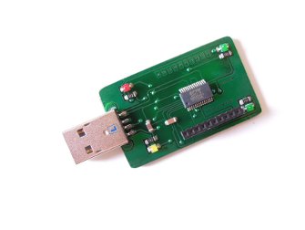
of assembling the SMD (surface
mounted devices). The print is connected directly to an USB port. To solder the FT232RL and the other components I use soldering paste. The results are excellent. |
|
enlarge the electronic schematics of the
"FT232RL_xBee"
|
| Pure Data |
| By
default the transmitter sends every 50ms data to the receiver and from
there to the [comport] object of the Pd patch. With the patch one has
the ability to change parameters of the PIC18F4220, us changing sample
rates or changing the trash hold and juicing the desired channel. The received data one can be resend to sound or video applications using [netsend], [oscsend] etc. Attached to the ZIP is included the Pure Data patch allowing to manage 3 channels of incoming data. |
| Galvanic skin response |
| Abbreviated GSR
(galvanic skin response)
is the conductance measured in S (Siemens not Seconds). Of the skin.
The human sweat glands act like electrical conductors in the way that
when the sweat glands are filled up with sweat the resistance lessees
(the conductance increases). If we use a DMM (Digital Multi Meter) and we press the two cables of the DMM against two fingers of one hand, we observe a oscillating result that can be between 50K and 2M ohm, depending of the emotional condition of the person. Human skin is a good conductor of electrical activity. In applying a small electrical current to the skin one can measure the changes in relation to the resistance (opposite conductance). A variety of stimuli, like touching the skin, ambient al stimuli like sound or smell or emotional stimuli like stress or happiness of a person can provoke a galvanic skin response. A curve of an emotion has a delay of approx. 1 second and a slow decay of several seconds. The clearness of the GSR depends of the intensity of the emotion. |
| schematics using a OPA336 |
| In my investigations
about GSR I found a
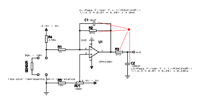
very simple circuit to experiment with. (link) Using only one OPA336 (or OPA2336) it is possible to measure GSR events. Adding two filters to the original schematics the circuit can be improved considerably. GSR events are slow, so, in eliminating frequencies above 5Hz and frequencies lower than 0,5Hz the measured signal is cleaned from undesired frequencies (noise). The capacitor C1 of 10nF and the resistance R2 of 3M3 act like a low pass filter, and the capacitor C3 of 100nF together with the resistance R3 of 3M3 behave us hi pass filter . To calculate the cut-off frequency: f = 1/R2*C1*2Pi). |
 |
|
enlarge the electronic schematics of the
"GSR_OPA336"
|
| How does it work? Applying a voltage (2.5V-5V) to the resistor R4, the same resistor together with the resistance of the skin (sensor) behave like a voltage devider. The result of the GSR event is afterwards amplified by 3,3 (Gain = R2/R1) and finally filtered by a low pass filter (R3, C2). With the potentiometer RV1 the voltage reference (Vref) of the OPA can be adjusted. |
| Wheatstone Bridge |
| The
original schematics is from: EDA
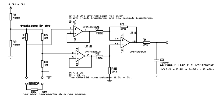
SENSOR Because of the very high human skin resistance a common way to measure the conductance is in using the Wheatstone Bridge represented with the resistance R3 of 3M and the resistance of the skin (sensor) and on the other side of the bridge with the resistance R5 and R6 of 3M respectively. Each half of the Op-Amp (U1A, U1B) behave us voltage followers. In this configuration we get the high impedance needed to not affect the small voltage delivered from the high resistance of the Wheatstone Bridge. The following Op-Amp is set us a voltage amplifier. The gain is calculated with Gain=Rfg/Rin. In our example (R9)2,3M/(R7)100K = (G)230. It is not clear why the guys from the EDA SENSOR project are using uncommon values for the resistors. Using values of 2,7M, 3,9M, 2,2M does not affect the performance of the circuit.To understand the circuit one has to understand the basic function of a differential Op-Amp: Only the difference of the inputs (In+, In-) is amplified. This kind of circuitry is often used when a long distance from a sound source (microphone) and an amplifier is involved. Sound installations in t heaters or PA systems for concerts use the advantage of this circuitry because of the simple and efficient manner to get rid of noise (Radio Frequencies etc.). The resistor R4 of 3M3 together with C3 of 0,1uF act us a low pass filter with a cut-off frequency of 0,48Hz. |
 |
|
enlarge the electronic schematics of the
"OPA_4336"
|
| INA333 la manera profesional |
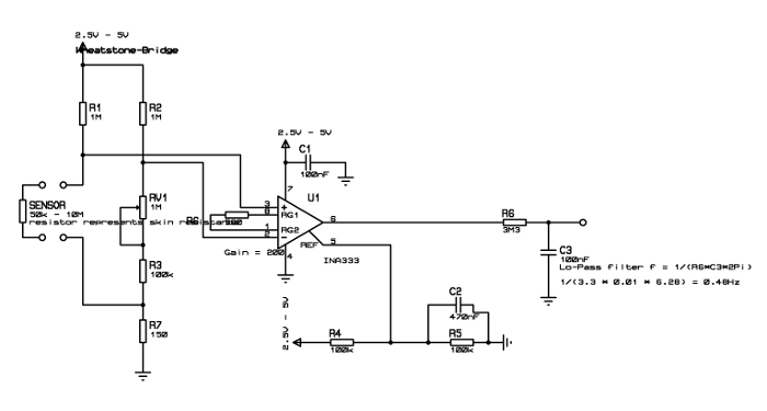
| El INA333. The circuit above /EDA SENSOR) is a common circuit to measure high impedance loads. For this reason it doesn’t surprise that Op-Amps with already three units (three Op-Amps) incorporated in one unit exists. The INA333 or INA121 Texasinstruments have the entire schematic from the above circuit integrated. An other famous company is Analog Devices with a variety of IC's. The schematics discussed here uses the INA333 together with a Wheatstone Bridge. With only one resistor the Gain is adjusted (R6) and with the potentiometer at pin 5 (in this case R4, R5 adjust the voltage at half of the power voltage) the offset trimming can be regulated. It is helpful ton read the data-sheet of the INA333. The entire circuit can be improved in adding another Op-Amp, an OPA333 for example, to add a low pass filter at the feedback of the Op-Amp and a high pass filter at the output of the circuit. (see the next example for the filters) The schematics discussed here has only a low pass filter with R6, C3 at the output of the circuit. |
 |
|
enlarge the electronic schematics of the
"GSR_INA333"
|
|
In case you plan to connect the circuit to a PIC, the Arduino for example, the filer R6/C3 is important to get accurate results. It is a good way to prove the effect of the filter in connecting a oscilloscope to the output. Immediately one understands the effect and importance of the filter. |
| another schematics with a voltage divider |
| Good results
I got with a schematics from SeanMontgomery. The
original schematics I changed in adding a Lo-pass filter at the output
(important) and changing the reference voltage with a simple voltage
divider. The voltage of the GSR event is evaluated with the resistor R3 of 1M and the resistance (conductance) of the skin. The optained votlage is filtered by U1A and the amplified bt 100 G=R7/R6 with the seconf half of the OPA2336, U1B. Es mentioned above the voltage reference (Pin3, and Pin5) is made with R1,R2 (150K). In this way when the batteries voltage goes down the Vref is always at half the power voltage. I don't know why Sean uses diodes (1N4148) to get the voltage reference (virtual GND). If the circuit is connected to a Arduino o Microchip on other low-pass filter at the output improves the results. The firmware of the PIC18F25K20 Sean Montgomery wrote acts like a low-pass filter of 3Hz.This is the reason he doesn’t has the need to put a low-pass filter in he's schematics. In any case if a PIC is used I recommend scanning the events with a frequency of approximatively 40Hz. The frequency of 40Hz is far enough for slow GSR events. You can do so programming the overflow bit of the TRM0. |
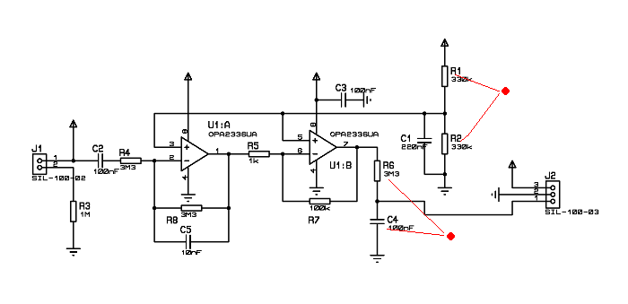 |
|
enlarge the electronic schematics of the
"GSR_OPA_2336"
|
|
|
| El PCB esta hecho con componentes tipo SMD (sourface mounted devices) para tener lo lo más pequeño posible. |
| los sensores |
|
|
| The above sensor is made with aluminium (chocolate) paper and a velcro. With a sawing machine the thin cables are fixed (cable of a PC bus). It is important to have good connection between the cable and the aluminium foil. With week connection it is impossible to get clear results of GSR events. I used this sensors now for month and I didn't have any problems because of bad connections. |
| other sensores |
| Very simple sensors using a virgin PCB cutting a gap of 3mm. One of this sensors I glowed with contact glow underneath the velcro. Attached to the leg, for example, the actor can move free in the room. |
|
|