RN171 & ANDROID |
|||
- page last modified, November
2015- (página en castellano)
|
Since
May 2013 COSM is XIVELY and since Octuber 2015 I get a server error
and there is no support for free account users of Xively. This is the reason that I moved to GroveStreams witch has a lot of nice features and a brilliant support (forum) with very clear API information. For all “arduiners” GS offers an entire code to upload data to GS. |
step
1: create a feed with GroveStreams |
Create a GroveStreams
feed. To get the ability to store, update and visualize data on a remote sever and to get access from any computer with Internet I created a personal free account. Following this useful tutorial https://grovestreams.com/developers/tutorial_temp at the support page of GS, one creates a Componet and its Streams with ease. |
step
2: connnecting the RN171 using GTK terminal |
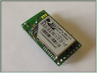
A small circuit is needed to communicate with the RN171. Watch out: The power for the RN171 is between 2V and 3,3V and shouldn't exceed 3,7V. If you accidentally put 5V the WiFly is flying to heaven. For experimenting purpose two 1,5V batteries work perfectly. |
|
The communication with the RN171 is done with a serial terminal (I use GtkTerm for LINUX) and a FT232RL. One can use also an ARDUIO board with a FT232RL incorporated. In this case connect the 3,3V & GND to it's equivalent at the RN171 and connect RX from the ARDUINO board to TX RN171 and the same with TX to RX. When experimenting with the RN171 WiFly I recommend to unplug the PIC. In this case the ARDUINO board is used only as a USB to USART converter. After the connection is done the GtkTerm has to be set to 9600 baud 8 bit, 1 stop bit and none parity. There is also an option to configure the WiFLy wireless with telnet. For this at boot the GPIO9 (pin 4) has to be connected to PW (3,3V). Depending on the firmware version the WiFly can then be acceded with: telnet 1.2.3.4 2000 telnet 192.168.1.1 2000 telnet 169.254.1.1 2000 Writing $$$ and then press enter, the WiFly will enter command mode. |
step
3: configure the RN171 |
The following configuration is done for a ANDROID HTC but can be adapted, of course, for any router. $$$ // enter command mode. Resp: CMD scan // returns the MAC addresses. Resp: <4.41> SCAN:Found 1 Num SSID Ch RSSI Sec MAC Address Suites 1 HTC Portable Hotspot 11 -68 WPA2PSK d8:b3:77:14:20:04 AESM-AES 1100 set wlan ssid <string> // fill spaces with $ (HTC$Portable$Hotspot) Resp: AOK <4.41> set
wlan auth 2
// 2 WPA2 security mode of HTC. set wlan phrase <string> // password for WPA / WPA2 (10 números). Resp: AOK <4.41> set wlan join 1
// wlan is started automatically. save // save the configuration. Resp: Storing in config <4.41> reboot Resp: *Reboot*WiFly Ver 4.41, 02-13-2012 on RN-171 MAC Addr=00:06:66:72:43:cd Auto-Assoc HTC Portable Hotspot chan=6 mode=WPA2 SCAN OK Joining HTC Portable Hotspot now.. *READY* Associated! DHCP: Start DHCP in 455ms, lease=43200s IF=UP DHCP=ON IP=192.168.1.52:2000 NM=255.255.255.0 GW=192.168.1.1 Listen on 2000 // The info reflects the connection to my Android Cell-Phone. exit Resp: EXIT $$$ // re-entering the command mode. Resp: CMD set ip dns grovestreams.com // Ip is 173.236.12.163 Resp: AOK <4.41> set ip remote 80 // the feeds port of GS. Resp: AOK <4.41> set sys autoconn 1 // automatic connect to GroveStremas after booting the WiFly. Resp: AOK <4.41> set uart mode 2 // if RX data enters the connection is made. Resp: AOK <4.41> set ip proto 18 // TCP & HTTP protocol. Resp: AOK <4.41> set comm remote 0 // no *HELLO* message confuses the server. Resp: AOK <4.41> save // save the configuration. Resp: Storing in config <4.41> exit Resp: EXIT // after booting the RN171 the unit connects to GS. |
transfer data
to GroveStreams: This simple example updates two stremas in a Component with the values 135 and 100. serial_printf("PUT /api/feed?compId=MyCompId&data=135&data=100&api_key=MyApiKey" |
PCB
with three sensors: light, temperature & sound |
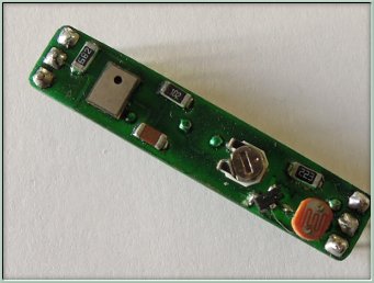
A very small PCB (7mm * 35mm) with 3 sensors. A standard LDR, a LM60CIM3 for temperature measurement and a SMD type microphone. All three sensors a connected to the analogical inputs of a PIC18F4420 and the 10bit result is sent every second to the USART of the RN171. |
enlarge
the electronic schematics of the sensors
|
base circuit for the
RN171, the sensors and the PIC18F4220 |
The heart of
the circuit is a PIC 18F4220. The sensors are connected to port RA0 –
RA2 configured as analog inputs and the USART of the PIC sends the data
to the RN171. Attached, on the bottom of the page is an entire MPLAB IDE file written in C for the Source Boost compiler with the source code. |
enlarge
the electronic schematics of the sensors |
|
download schematics and source code |