The
circuit has incorporated a Li-Ion battery, a MAX1555 and a LDO TPD 7933
(low drop voltage regulator for the WiFly RN171).
Also, one can plug in a variety of smaller circuits using the available rows of pins.
|
Atmega328 with a WiFly RN171 |
|||
|
- page last update July 2013- (página
en
catellano)
|
| the page
includes: - a general description of the circuit. - connecting a FT232RL to a Atmega328 using a mini-USB. - upload a "bootloader" with a AVRISP mkII programmer. - a link to the schematics of th e circuit. - how to program the Atmega328. - basic program to test the Atmega328. - how to connect the WiFly to a Local Area Net. - a Pd patch the read data from the WiFly. - code for SuperCollider to receive data from the WiFly. |
|
a general description of the circuit |
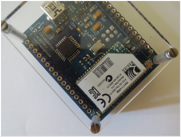
| The
size of the compact design is only 5cm * 4,3cm (the size of the
UNIROSS, 700mA Li-Ion battery) and has a similar concept as the
previous circuit link which
incorporates a Nordic nRF24L01 as a wireless radio. The big advantage
using a WiFly is that the unit can be connected to any computer with
a WiFi module and there is no need for a receiver unit. The price of the WiFly RN171 is 23E. If one compares the price for a red with the xBee Znet at 40E (2 units needed) or the Easy Radio for 23E per unit the WiFly is quit cheap solution, but still expensive comparing to the Nordic nRF24L01 for 3,50E. If one has the ability to solder this Nordic (a reflow oven is needed) the wireless solution is cheap, but there is always the need of two units. Very handy is that the PCB has a MAX 1555 battery charger incorporated that allows to charge the battery from a USB plug. The same mini USB is also used to program the Atmega328. One needs a level shifter, a FT232RL, to program the Atmega. The Arduino LilyPad is programed the same way as the here presented circuit (link) and to connect the mini USB to the FT232 circuit one needs a USB cable with all 5 pins connected. I made my cable myself. |
| connecting the FT232RL
to the Atmega328 using a mini USB cable |
| PCB
FT232: TXD > RXD Atmega328 pin
30. PCB FT232: RXD > TXD Atmega328 pin 31 PCB FT232: CTS > RESET Atmega328 als RST cap C7. (consult schematics) PCB FT232: 5V > 5V mini USB ( consult schematics) PCB FT232: GND > GND mini USB (consult schematics) |
| Beside: The newer Arduino have the level shifter FT232Rl replaced with on other Atmega that is, in a technical sense, discussable but has the advantage of the price (the FT232RL is expensive) and opens up the possibilities to send data in different formats to the USB, like MIDI. In any case having two micro-controllers mounted on one PCB is not really happening, because things could be done with only one PIC. |
|
The
circuit has incorporated a Li-Ion battery, a MAX1555 and a LDO TPD 7933
(low drop voltage regulator for the WiFly RN171).
Also, one can plug in a variety of smaller circuits using the available rows of pins. |
|
Before the Atmega328, or any Atmga, can be programmed with a FT232RL (the older Arduino had the FT232Rl incorporated) a bootloader has to be installed. |
| install the bootloader using a AVRISP mkII programmer |
|
The easiest way to upload the bootloader is using the Arduino IDE. The price for a AVRISP mkII is 28E. To upload the bootloader the circuit has a 6 pin ISP connector incorporated. The AVRISP mkII is powered through the USB, but take care, to upload the bootloader the Atmega328 has to be powered with the battery or throughout the mini USB. |
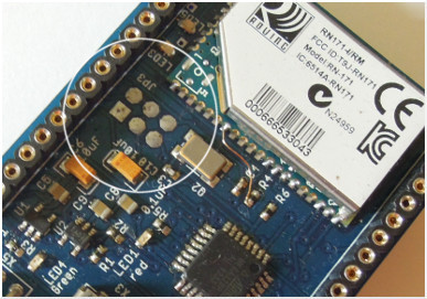 |
Because of the hight of the pins, after the bootloader was installed, I unsoldered the ISP connector (JP3). The connection of the pins are shown in the attached electric schematics (down the page) More information: http://www.arduino.cc/en/Hacking/Bootloader |
| enlarge the electronic schematics of the circuit |  |
| program the Atmega328 |
| program the
Atmega328
and configure the ports & A0 as analog read.
Before one can configure the WiFly RN171 in a wireless manner, several ports of the Atmega328 have to be set. First: that the WiFly RN171 connects automatically to a Local Area Net and that one is able to configure the unit using a terminal (shell), the GPIO_9 pin (pin 4) hast to be connected to 3V. Second: the Pin 14 of the Atmega (PB2) has to be set to high to enable the LDO and to power up the WiFly.
The following code can be uploaded using the evireoment of the Arduino IDE. The serial port has to be selected: Tools > Serial Port > dev/ttyUSB0 (in my case) and select the Borad > Arduino Pro o Pro Mini (5V, 16MHz) w, Atmega328. |
| basic code for the Atmega328 |
| /* Analog read for PH probe 10 bit. Reads an analog input pin, ANALOG PIN 0 and sends the data to the serial port. Protocol: The protocol is a three byte data package, Header = 0; PhHi = Hi-byte of 10 bit & address (64 addresses max) PhLo = Lo-byte. The circuit: * Connect the PH probe to the AN0 (analog 0) created 22 May. 2013 Martin Hug */ // variables declaration: const int analogInPin = A0; // Analog input pin that the Ph probe is connected. int sensorValue = 0; // 10bit value read from the PH probe. byte address = 4; // 00000100, first possible address. byte PhLo = 0; // Lo-byte of 10 bit data. byte PhHi = 0; // Hi-byte of 10 bit data. void setup() { // set PORTB, GPIO_9 del WiFly (PB0), LED (PB1) & 3V(PB2). DDRB = B00000111; Serial.begin(9600); } void loop() { PORTB = B00000111; // WiFly connect to local red, LED ON , 3V ON. sensorValue = analogRead(analogInPin); PhHi = address | sensorValue>>8; // merge adddress and upper byte. PhLo = sensorValue; // lower byte. // print the results to the serial monitor: // Use Serial.println ASCII for(Pd) and Serial.write DECINAL for SuperCollider (and Serial Monitor). // for Pd-extended Serial.println(0); // header byte. Serial.println(PhHi); // first byte. Serial.println(PhLo); // second byte. // for SuperCollider /*Serial.write(0); // header byte. Serial.write(PhHi); // first byte. Serial.write(PhLo); // second byte.*/ delay(50); // increase value for slower data transfer. } |
| connect
the WiFly RN171 to a Local Area Net |
|
Once you uploaded the bootloader, and programed the Atmega328 with the above code, and after reseting the unit the LED's of the WiFly blink and also the red LED is on. Ones reached this point the only thing to do is to connect the WiFly to the Local Area Net. Of course this only works if the computer has a wireless WiFI card. We rest the wireless network of the computer (after powering up the circuit) and we look for WiFly-EZX-43 or similar (I have a second one called WiFly_GSX-cd). Once the connection is done we'll try whether we can communicate with the WiFly. Using a terminal: telnet 1.2.3.4 2000 o para el GSX-cd: telnet 169.254.1 2000 telnet 1.2.3.4 2000 Trying 1.2.3.4... Connected to 1.2.3.4. Escape character is '^]'. *HELLO* If we get *HELLO* we know that the connection is established. |
|
a "patch" for Pd-extended to read data from a WiFly |
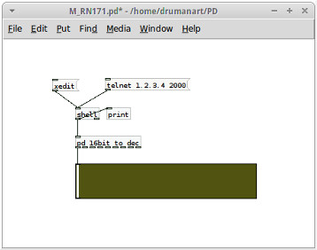 |
All what can't be seen at the image is included in
the ZIP file what can be downloaded at the bottom of the page. With the
patch one can simultaneously receive 8 channels of data.3 byte protocol to get a resolution of 10bits and 6
bits addressing. From the WiFly 3 bytes are sent: 1.B00000000: header; // byte de inicio 2.B000000DD: DD Hi-Byte of 10bits (0 address) 3.BDDDDDDDD; DDDDDDDD Lo-Byte. |
| code for SuperCollider to receive data from the WiFly |
| ( ~pipe = Pipe.new("telnet 1.2.3.4 2000", "r"); Routine({ var byte, address, loByte, hiByte, val, chan, index= 0, toUnsignedByte; inf.do{ toUnsignedByte = {arg x; ((x < -128) || (x > 127)).if {}; (x < 0).if {256 + x} {x} }; while({byte = toUnsignedByte.(~pipe.getChar.ascii); byte.isNil}, {nil}); //wait for data. if(index==0 and:{byte==0}, { index= 1; }, { if(index==1, { hiByte= byte; index= 2; }, { if(index==2, { loByte= byte; chan= (hiByte&2r11111100)>>2; // mask 2 lower data-bites val= ((hiByte&2r00000011)<<8)|loByte; ("chan:"+chan+"val:"+val).postln; ~action_gui.value(chan, val); index= 0; }); }); }) }; }).play; ) // // thanks to Glen Fraser and Sam from llucec.org for help. |
| |
|
HTML
Comment Box is loading comments...
|
|
|
 |
dowload the schemmatics and the code for the Atmega
328 |